Welcome to Henan Zhongyide Intelligent Technology Co., LTD

Welcome to Henan Zhongyide Intelligent Technology Co., LTD

Product Center
CONTACT US
air lock rotary feeder
Structure
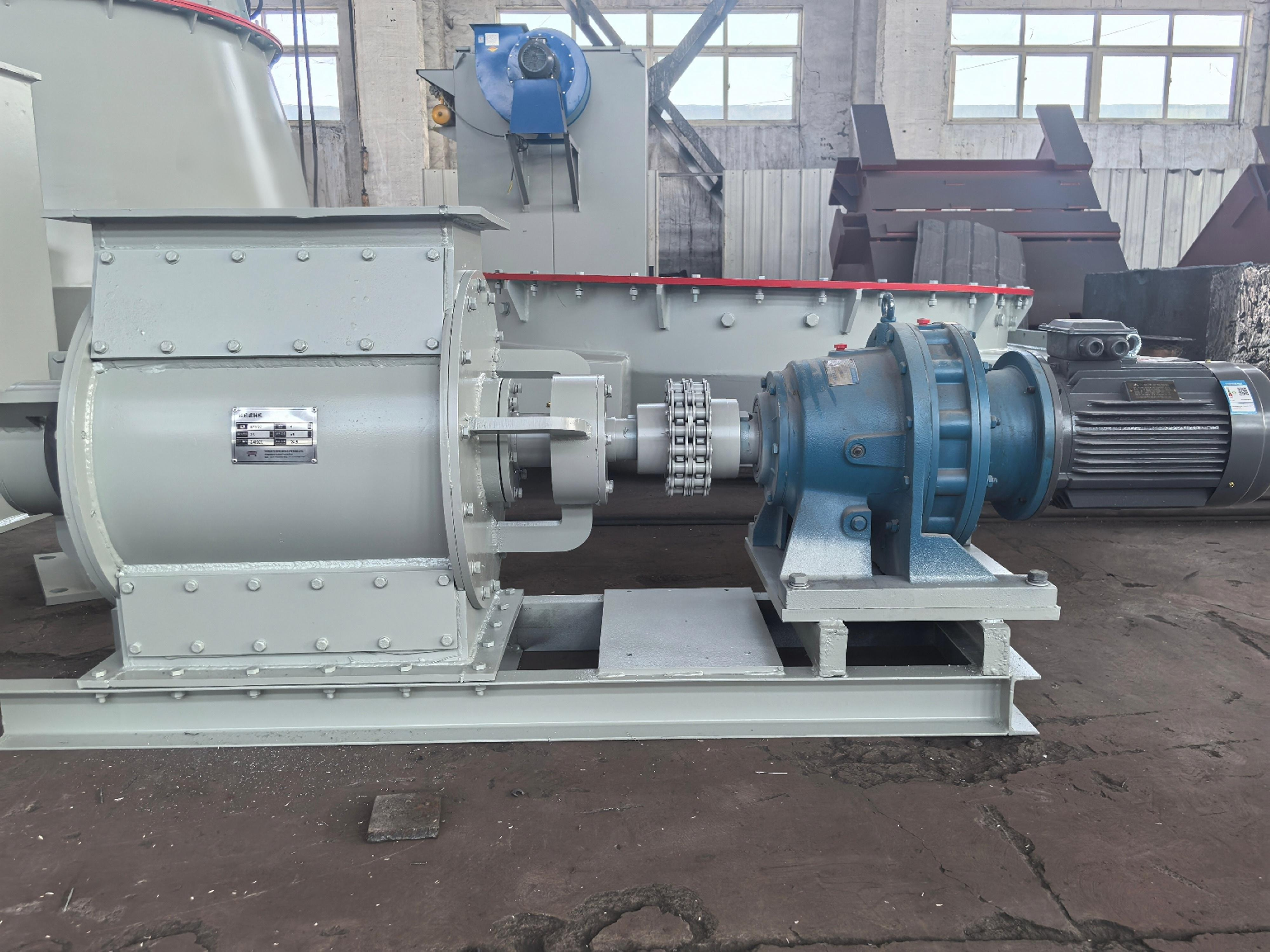
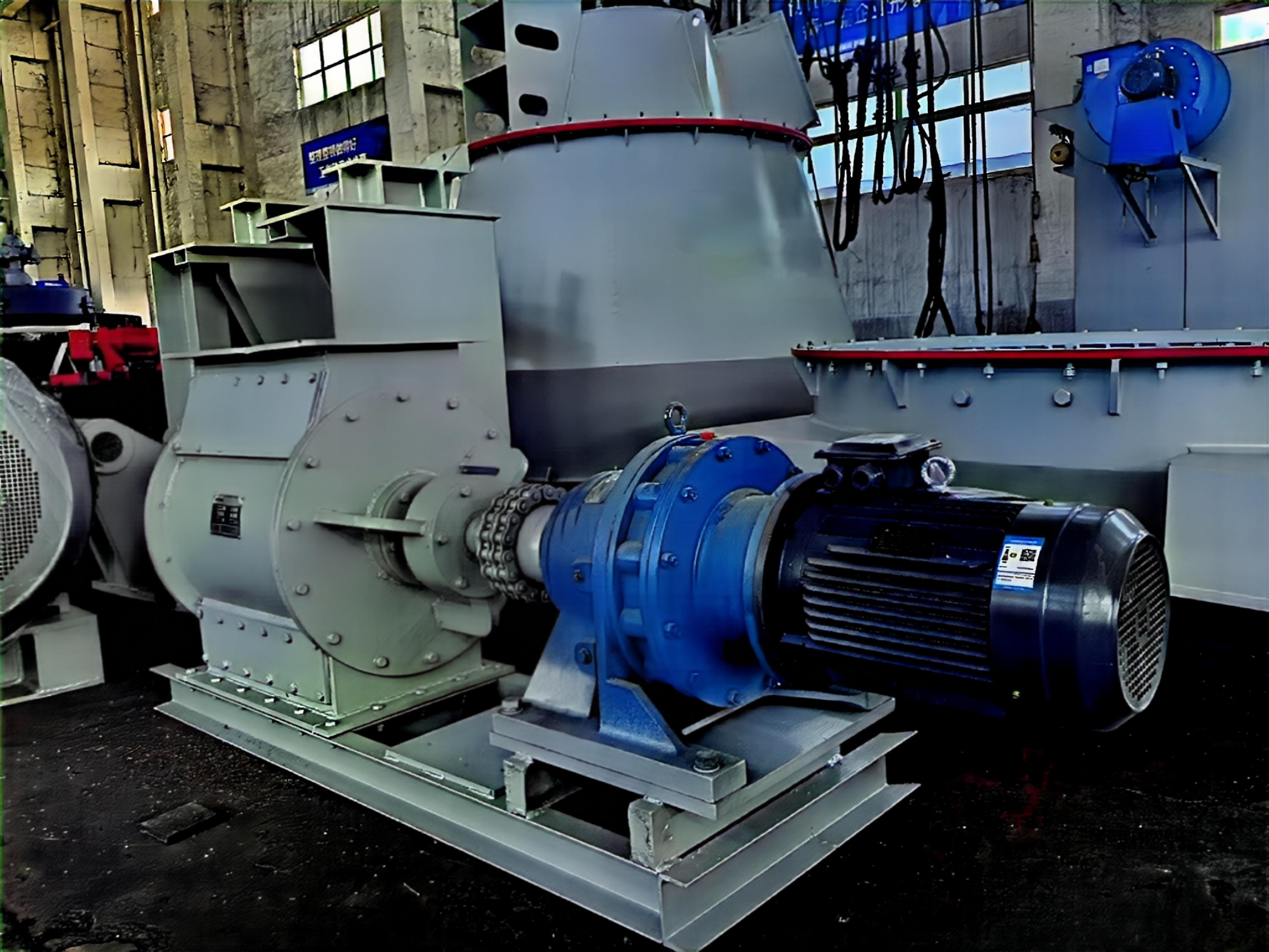
This air lock rotary feeder is composed of housing, a rotor (rotating impeller), a driving device, etc.
Working principle
The feeder has a multi-bladed rotor inside. The material in the upper rotating airlock feeder hopper falls under its own weight, filling the gaps between the blades. The material is then discharged from the lower feed port as the rotor rotates. Because the space between the rotor blades is uniform, the rotor speed is constant.
The inner lining of the rotary airlock feeder housing of the vertical mill is mostly equipped with an anti-wear layer; the impeller is supported by bearings at both ends, which ensures a uniform gap between the impeller and the housing. The two ends are sealed with asbestos packing, which is simple, has good sealing performance, and is easy to operate and replace.
The rotary air-lock feeder for the vertical mill is equipped with hot air channels. When the feed material has high moisture content, a layer of powdery material may adhere to the bottom of the impeller; introducing high-temperature gas dries this material, preventing adhesion and ensuring the feed rate remains unaffected (the air inlet and outlet should be sealed off when not in use). For feeders with a diameter of 1800 mm or larger, one or two access doors are provided on the side of the casing; these can be opened as needed to inspect the interior and replace the wear-resistant liners on both the casing wall and the impeller. Additionally, inspection ports allow for clearing debris, resolving blockages, or addressing other issues that disrupt normal operation. They also facilitate monitoring of the feed status. The equipment typically operates with a bucket fill level of 30–50%; overloading must be avoided, as the fill level is regulated by the impeller's rotational speed. Higher speeds result in less material per bucket, while lower speeds result in more; the fill level must be kept within the 30–50% range, as exceeding 50% increases the risk of jamming and potential damage to the drive mechanism.
Technical Specification
Specification | Nominal Displace(L/R) | Filling Rate(%) | Feeding amount(m³/h) | Rotor Speed(r/min) | Motor Power (KW) |
HSFW50*50 | 78.5 | ≤40 | ≤20 | 10.6 | Y132M1-6/4 |
HSFW65*65 | 172 | ≤40 | ≤40 | 10.6 | Y132M1-6/4 |
HSFW80*80 | 320 | ≤40 | ≤70 | 9.217 | Y1325-4/5.5 |
HSFW100*100 | 620 | ≤40 | ≤125 | 9.217 | Y1325-4/5.5 |
/ 86+13838200416
( Telephone )